Land Rover - Electrical bits, transfer case sump, other small jobs
Adding fuses
After driving the Series II around for a while and getting reasonably comfortable with it, I realised I was a bit nervous about driving it in the rain. The main problem was the fuse situation. From the factory, there is only one fuse for the entire car, protecting the windscreen wiper, brake lights, and fuel level sender. I’m not sure why the engineers originally chose to protect only these (and not, say, the headlights) but that’s how it is.
Later models had more fuses, and more electrical equipment protected. With this in mind, I chose to add a few subtle inline-style fuses for various components:
- 5A fuse for the side lights
- 10A fuse for the tail lights
- 10A fuse for low beam
- 10A fuse for the brake lights
- 15A fuse for high beam
- 30A fuse for the main wire from the starter switch to the ammeter
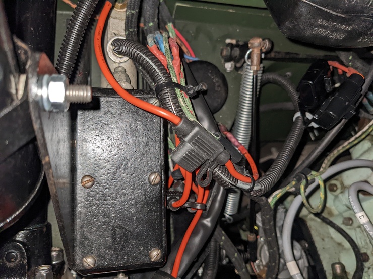
This doesn’t quite cover everything, but it’s a lot better than it was. The 30A fuse on the wire from the starter switch to the ammeter is something of a “catch-all”, it’s still possible for damage to occur in the time it’ll take to blow (for example, the lead lamp sockets) but I’m confident it’ll prevent a fire, at least.
The main issue I now have with driving in the wet are the skinny 6.00x16 bar tread tyres, which don’t offer a lot of grip.
Bad ground
While installing fuses and testing them, I noticed that the main beam warning light in the dash wouldn’t turn on. The main beams themselves worked fine, so it wasn’t the lights or the switch. Measuring the voltage at the dashboard indicated the junction box was at least trying to send current to the warning lamp.
After unbolting the dashboard and pulling it forward just enough to reach behind it, I removed the housing for the warning light and tested it on the bench. Curiously, it worked fine - so where was my electrical problem?
I removed the larger instrument binnacle to test that independently with a DC power supply, and found that moving the ground from the bulb socket to the “common” ground point on the screw holding the cluster to the dashboard prevented it from working.
I forgot to take photos of the process while I was doing it, but here’s an old picture of the instrument cluster in question, before I restored it.
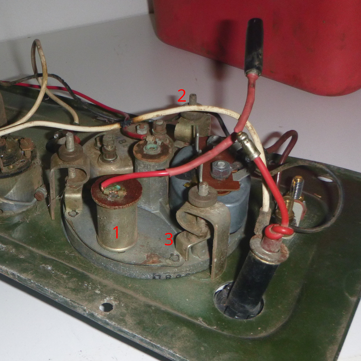
The part labelled (1) is the main beam warning light, the part labelled (2) is the common ground, and the part labelled (3) turned out to be the answer. It turns out that the “bridge” between the segments of the gauge cluster needs to make good electrical contact, they’re not just for distributing clamping force. The segments are isolated from the main body with a rubber gasket, so there’s no ground through the cluster body without those bridges.
Once I discovered that, it was a ten second job to fix it: remove the clamp, clean off some of the dust that had gotten under it (or was already under it), and fasten it back to the vehicle.
New transfer case sump
As mentioned in the previous blog post, I’ve fitted a Wootz transfer case sump.
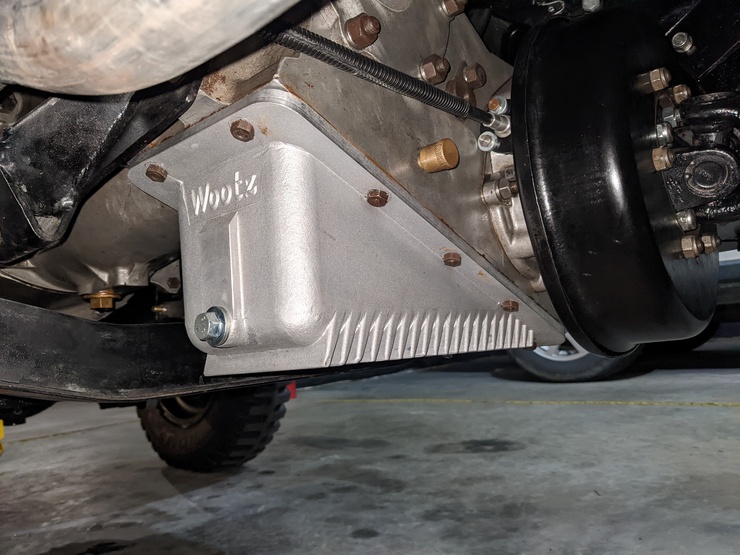
So far I’m very happy with it, it’s fixed the (very) slow drip when parked and the slightly faster drip when hot. I haven’t measured the temperatures before and after, but given the extra oil capacity and cooling fins, there’s no way it’s gone up.
The instructions suggest fitting it without a gasket, but unless you’re very confident that the mating surface of the transfer case is flat, I’d suggest using one. Some of these vehicles are over sixty years old, and the normal variations in the surface that creep in over time are unlikely to line up with the freshly-machined sump.
Other jobs
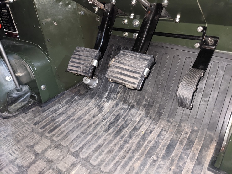
Now that I’ve gotten comfortable with it, I wanted to revisit the accelerator pedal setup. There were a few issues with the initial settings I made during restoration, none of which were foreseeable (unfortunately). Firstly, the pedal was in a bad place for the “heel and toe” manoeuvre needed on a non-syncromesh gearbox, so my “third to second” and “second to first” changes were sometimes a little crunchy.
The second issue was that it left a little bit of throttle on the table right at the end of its travel, meaning I only had 90% throttle when flooring it. This wasn’t a big issue, but it’s not optimal. After disconnecting it at the carburettor end and playing with the linkages, I discovered the problem was at the arm on the end of the shaft from the pedal to the outside of the toe box. There wasn’t quite enough clearance between the mounting bracket and the tensioning bolt, so I moved it over a little. I also moved the accelerator pedal upwards a little, and I’m very happy with it now. Apologies for the bad pictures, it’s a difficult spot to photograph. The alt text for the image might be useful.
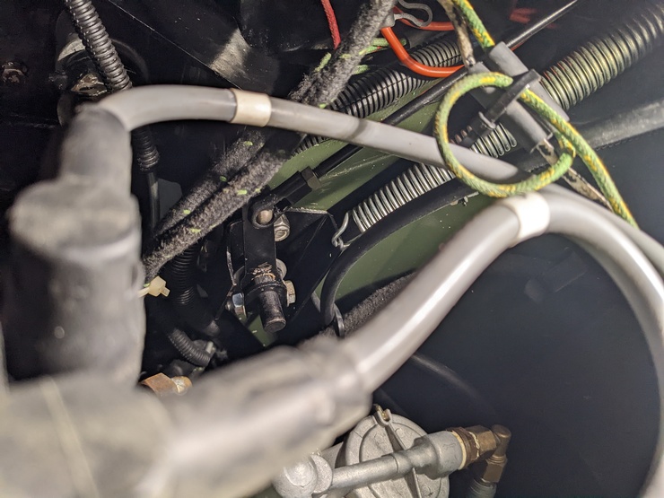
One unexpected benefit is that the linkages now sit slightly more square to each other, so throttle response just off idle has improved slightly.
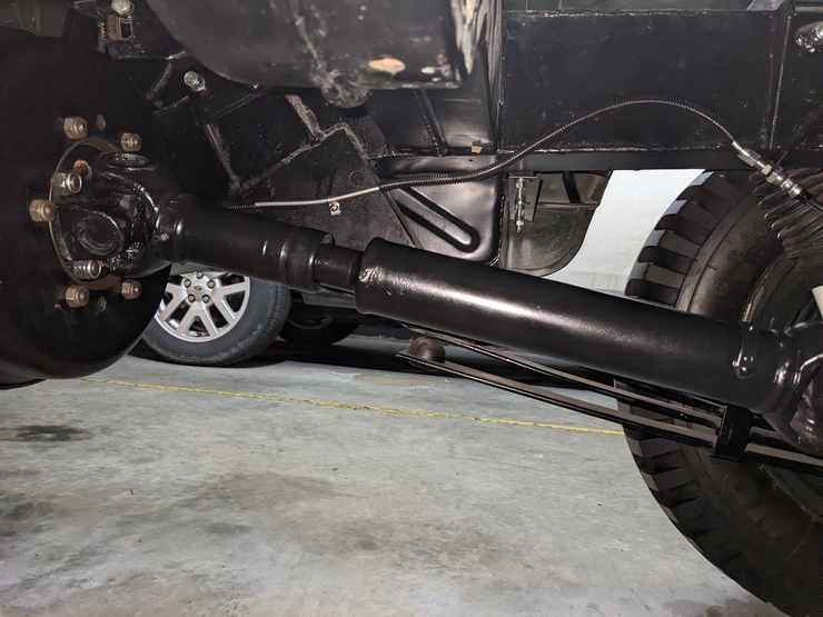
I also got the driveshafts balanced. This is something I should’ve done during the restoration originally, but there weren’t any driveshaft shops nearby and I had no means to transport them. In any case, they’re a 30 minute job to remove. I’m now a five minute walk from a driveshaft shop, so getting those balanced has fixed a slight vibration above 60km/h.